More Powerful MCU
The ESP32-S3R8 offers 8MB of PSRAM and is equipped with an external 16MB Flash, making the upgraded memory configuration more suitable for Ul and complex system design.
HomeProductsWiFi LoRa 32 V4.3 -- R8
WiFi LoRa 32 V4.3 -- R8
ESP32S3R8 + SX1262 LoRa Node, Meshtastic, MeshCore and LoRaWAN Compatible
BoardLoRaWi-FiBLE/BT
01 / 03
$21.90 — $29.50
The WiFi LoRa 32 V4.3 -- R8, the next gen to the Heltec V3, is a powerful, high-efficiency IoT maker board featuring an ESP32S3R8 MCU and SX1262 LoRa Node chip; retaining the V3’s size and identical pinout, it integrates performance upgrades including a built-in Wi-Fi/Bluetooth antenna, 28±1dBm LoRa output power, and a protected OLED display; its superior RF and stable system design ensure it’s ready-to-use and highly beginner-friendly, supporting development via Arduino, PlatformIO, ESP-IDF, and MicroPython; making it ideal for long-range wireless open-source projects like Meshtastic, LoRaWAN, and Meshcore in applications such as smart cities and industrial control, with custom hardware available on the Heltec MQB platform.
You May Also Like
06 picksExplore all products
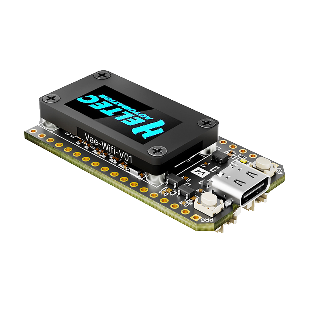
WiFi LoRa 32 V4.3 -- R2
ESP32S3R8 + SX1262 LoRa Node, Meshtastic, MeshCore and LoRaWAN Compatible
$17.90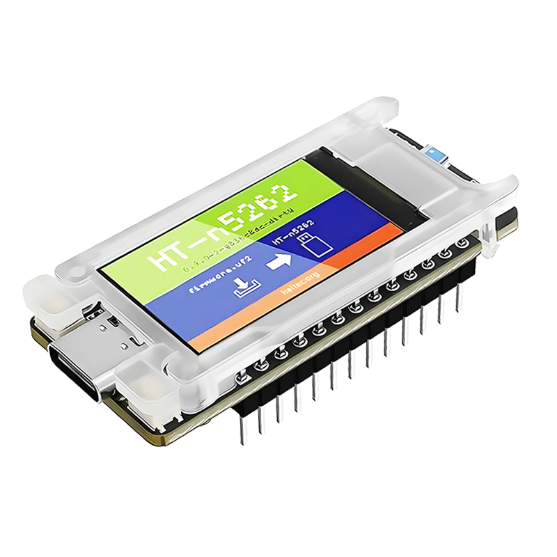
Mesh Node T114 (Rev. 2.0)
nRF52840 + SX1262 LoRa Node, Meshtastic, MeshCore and LoRaWAN Compatible
$17.90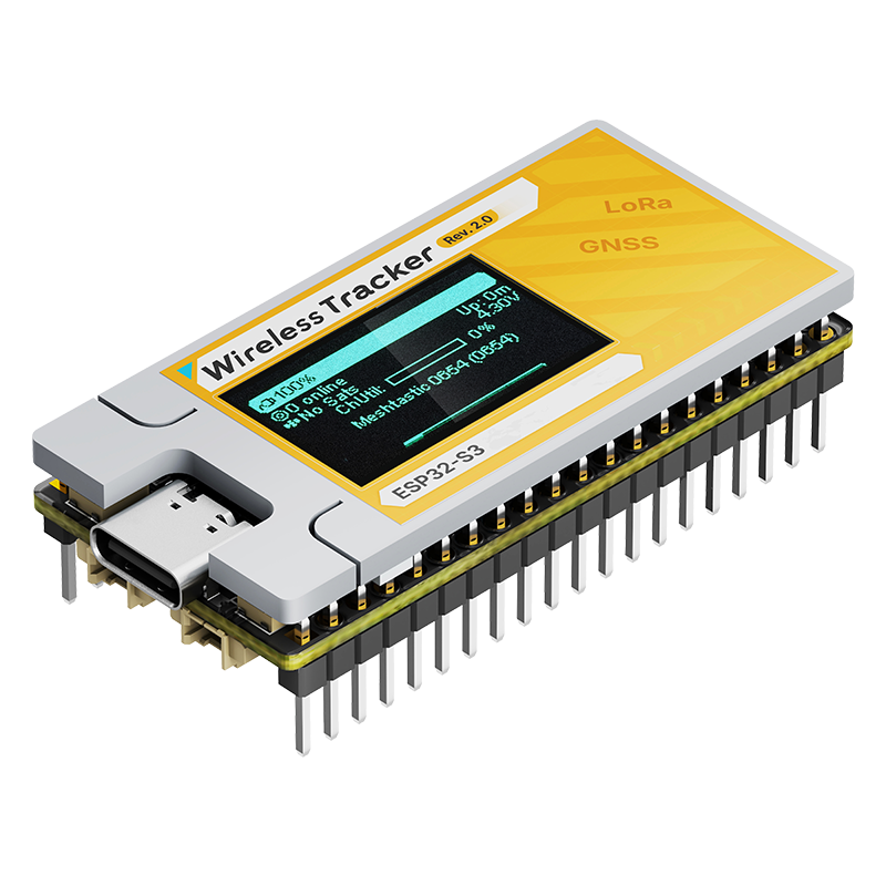
Wireless Tracker V2
ESP32-S3 +GPS+LoRa Node, Meshtastic, MeshCore and LoRaWAN Compatible
$30.90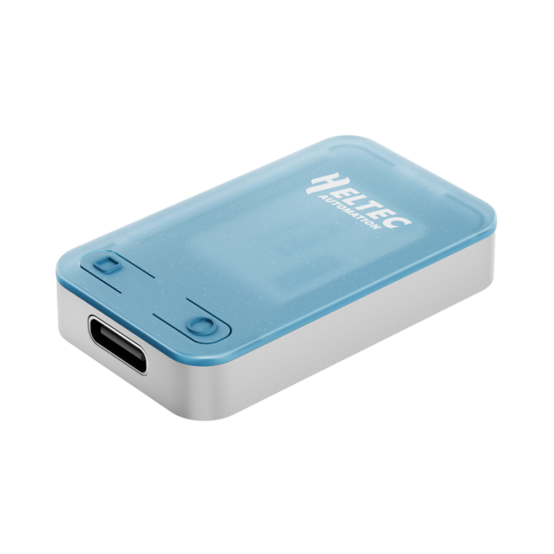
RadioCore RC32
RadioCore ESP32-S3 LoRa Wi-Fi HaLow, Meshtastic, MeshCore, LoRaWAN
$9.90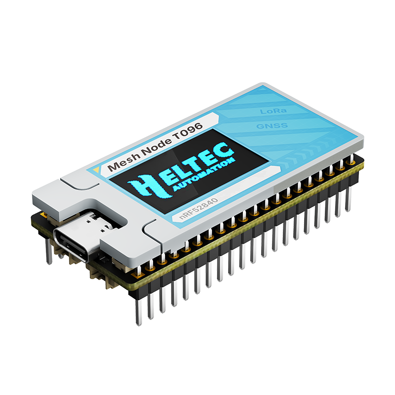
Mesh Node T096
nRF52840 +GPS+LoRa Node, Meshtastic, MeshCore and LoRaWAN Compatible
$33.90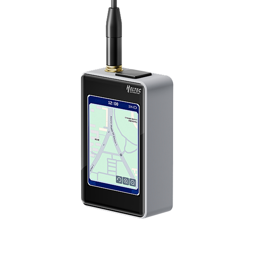
WiFi LoRa 32 V4.3 (R8) Expansion Kit V2 - Touch Screen
Multifunctional expansion enclosure designed specifically for the WiFi LoRa 32 V4.3 - R8
$66.90Compare Difference
Current product
WiFi LoRa 32 V4.3 -- R8
Before You Buy
- The WiFi LoRa 32 V4.3 now comes in R2 and R8 versions. This page is the WiFi LoRa 32 V4.3 - R8 version, which features the ESP32S3R8 as its main chip.
- Please check the table below to choose the right model.
| Parameters | WiFi LoRa 32 V4.3 -- R2 | WiFi LoRa 32 V4-R8 -- R8 |
|---|---|---|
| MCU | ESP32-S3R2 | ESP32-S3R8 |
| PSRAM | 2MB | 8MB |
| Merits | Extra free pins | Ideal for heavy-load tasks |
| Meshtastic | Name: firmware-heltec-v4-xxxx, version higher than 2.7.20 | Name: firmware-heltec-v4-r8-xxxx Version higher than 2.7.25, Temporary Download, |
| MeshCore | Version higher than 1.15 | Awaiting Merge | Temporary Download |
Summary
The WiFi LoRa 32 V4 -- R8, the next gen to the Heltec V3, is a powerful, high-efficiency IoT maker board featuring an ESP32S3R8 MCU and SX1262 LoRa Node chip; retaining the V3’s size and identical pinout, it integrates performance upgrades including a built-in Wi-Fi/Bluetooth antenna, 28±1dBm LoRa output power, and a protected OLED display; its superior RF and stable system design ensure it’s ready-to-use and highly beginner-friendly, supporting development via Arduino, PlatformIO, ESP-IDF, and MicroPython; making it ideal for long-range wireless open-source projects like Meshtastic, LoRaWAN, and Meshcore in applications such as smart cities and industrial control, with custom hardware available on the Heltec MQB platform.
Video
Main Features
- Based on ESP32-S3 & SX-1262, supports Wi-Fi b/g/n, BLE, and LoRa communication.
- LoRa Transmit Power: High-power version 28 dBm, Low-power version 22 dBm.
- PC casing protects the screen and integrates an FPC 2.4G antenna.
- Form factor and pin compatibility with WiFi LoRa 32 V3.
- PC casing protects the screen and integrates an FPC 2.4G antenna.
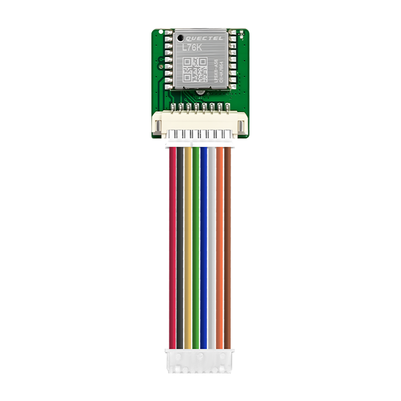
- Added 1.25-2-pin solar panel interface and 1.25-8-pin GNSS interface.
- Optimized lithium battery management.
- Low power consumption is less than 20μA.
Product Block

Specifications
| Parameters | Description |
|---|---|
| MCU | ESP32-S3R8 |
| LoRa Chip | SX1262 |
| Frequency | High-power version: 863-928MHz |
| Low-power version: 433-510MHz | |
| Wi-Fi | 802.11 b/g/n, up to 150Mbps |
| Bluetooth | Bluetooth (LE), Bluetooth 5, Bluetooth Mesh |
| Hardware Resource | 7 x ADC1 + 2 x ADC2; 7 * Touch; 3 * UART; 2 x I2C; 2 x SPI; etc. |
| Memory | 384KB ROM; 512KB SRAM; 16KB RTC SRAM; 8MB PSRAM; 16MB Flash |
| Interface | Type-C USB; 1.252 Pin lithium battery interface; 1.252 Pin Solar interface; 1.25*8 Pin interface; LoRa ANT(IPEX1.0); 2.4G ANT(IPEX1.0) |
| Battery applicable | 3.3 - 4.2V lithium battery |
| Operating Temperature | -20 - 70 ℃ |
| Dimensions | 51.7 * 25.4* 10.7mm |
Pin Map

Highlight
1 / 4
Packing List
The default packing list without selecting any accessories is as follows:
| Item | Quantity |
|---|---|
| WiFi LoRa 32 (V4) | x1 |
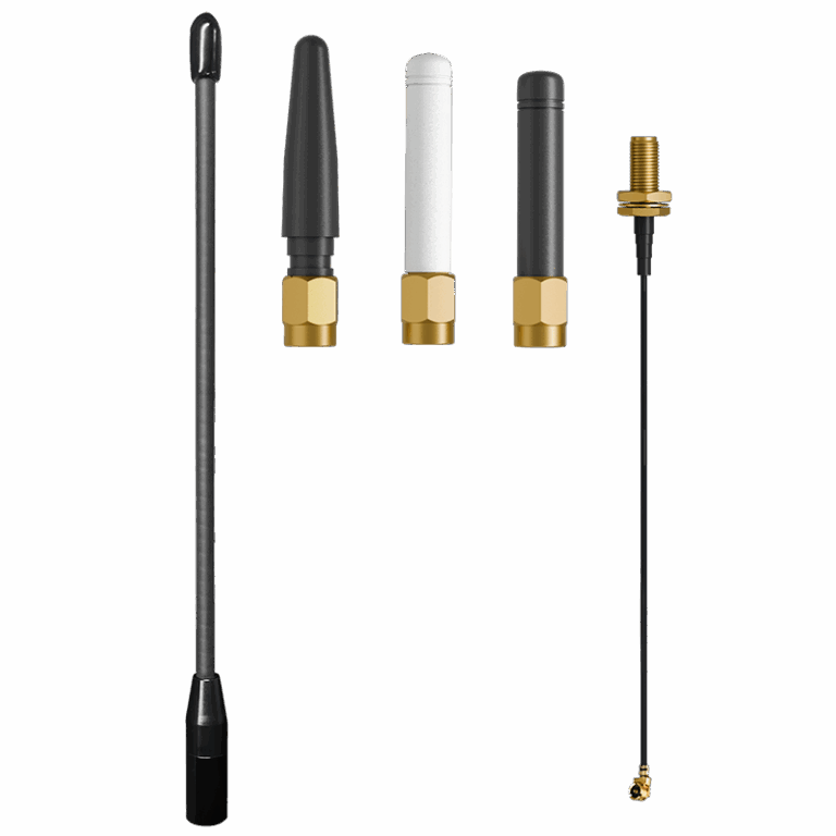
| LoRa Antenna | x1 |
| 1.25×2 Connector (for battery&solar) | x2 |
| 2.54*18 Header Pin | x2 |
FAQ
Q01Failed to flash firmware or upload code
Heltec Support
1.Enter BootLoader mode: Connect the USB-C cable, hold down the PRG button, press the RST button once, then release the PRG button.
2.Replace a USB data cable.
3.Change the port on the computer.
Q02German Warehouse Supported Countries/Regions (Click to View)
Heltec Support
Austria, Belgium, Bulgaria, Croatia, Czech Republic, Denmark, Estonia, Finland, France, Germany, Hungary, Ireland, Italy, Latvia, Lithuania, Luxembourg, Malta, Netherlands, Norway, Poland, Portugal, Romania, Slovakia, Slovenia, Spain, Sweden, Switzerland, United Kingdom
Q03US Warehouse Supported States/Regions (Click to View):
Heltec Support
South: Alabama, Arkansas, Delaware, Florida, Georgia, Kentucky, Louisiana, Maryland, Mississippi, North Carolina, Oklahoma, South Carolina, Tennessee, Texas, Virginia, West Virginia
Midwest: Illinois, Indiana, Iowa, Kansas, Michigan, Minnesota, Missouri, Nebraska, North Dakota, Ohio, Pennsylvania, South Dakota, Wisconsin
West: Arizona, California, Colorado, Idaho, Montana, Nevada, New Mexico, Oregon, Utah, Washington, Wyoming
Northeast: Connecticut, District of Columbia, Maine, Massachusetts, New Hampshire, New Jersey, New York, Rhode Island, Vermont
Not Supported: Alaska, Hawaii, Puerto Rico
Q042.4GHz Antenna
Heltec Support
For the screenless version, the 2.4 GHz antenna is connected to the IPEX connector by default.
For the OLED version,The default 2.4G FPC antenna is located on the side of the plastic screen bracket.
Hardware 4.2
If you wish to use an IPEX-connected 2.4G antenna, you need to remove the inductor marked as①in the diagram below, and add a 0-ohm resistor (or other conductive metal or cable) at the position marked ② to connect to the IPEX interface.
Hardware 4.3
move the resistor from Mark 2 to the position of Mark 1
Why is it designed this way?
By default, it is connected to the onboard FPC, and its circuit has been tested to achieve optimal performance. When you switch the resistor to IPEX, the IPEX connector will achieve optimal performance.
If both the IPEX interface and the FPC contacts are connected at the same time, the communication performance on both sides will be degraded.
This is a 0-ohm resistor. If you don’t have high requirements for the 2.4G signal, you can directly use a soldering iron to short-circuit both directions at once, making both sides work simultaneously.
Q05My screws look a bit odd?
Heltec Support
This area is attached with a 2.4G FPC antenna,and to avoid affecting its performance, customized plastic screws are used here.
That’s why they look different from ordinary screws.
When you need to remove it, gently press and turn with a screwdriver.
Q06What development methods does it support?
Heltec Support
- Arduino
- Micro Python
- Platform.io
- Espressif IDE We strongly recommend using Arduino. We have complete technical support and provide complete LoRaWAN code for ESP32 Arduino framework.
Q07What’s the battery socket type?
Heltec Support
You can find this type of socket by search “SH1.25 x 2”.
Q08Are V3 and V4 compatible?
Heltec Support
They are compatible in most scenarios.
Since V4 uses the same series of chips as V3, features the same OLED, and has an almost identical pin layout, V3 and V4 can be used interchangeably in the majority of cases.
However, due to the increased transmit power, the transmit power settings in some code may no longer correspond directly to the actual output.
Q09Why are there no resistors soldered on the 868 and 915 markings? Which frequency band does my device actually support?
Heltec Support
It indicates simultaneous support for both 868 MHz and 915 MHz frequency bands.
In the initial design, we developed two separate hardware versions to achieve optimal RF performance. However, through subsequent debugging, we have successfully unified the hardware for both 868 MHz and 915 MHz while maintaining excellent RF characteristics.
Q10“LoRa Error”
Heltec Support
It does not indicate device damage. Please disregard this phenomenon. The LORA ERROR occurs because it is running the factory default LORA testing program and cannot find another device running the same program.
Q11Firmware for V4.3
Heltec Support
- The standard V4 and V4-R8 use different firmware.
- When flashing Meshtastic firmware via Webflasher, the “Meshtastic UI” option is intended for the touchscreen version. Do not select this option for standard V4 boards.
Q12The screen does not display
Heltec Support
Please note: “Meshtastic UI” is for use with the touchscreen. For ordinary OLED screens, please do not select it.
Q13SAW filter
Heltec Support
Remove R32, mount 0Ω resistors on R37 and R38, then solder the SAW filter on U10.
Q14LNA for V4.3
Heltec Support
Note: The following content only applies to hardware V4.3 and above
-
Meshtastic 2.7.20: On the device, use the PRG button to navigate to “System” → “LoRa”, where you can choose to enable or disable LNA.
-
MeshCore 1.15.0: LNA is enabled by default and cannot be modified.
- You can download the firmware from this link, which has LNA disabled by default: LNA Disable
- With the firmware from this link, LNA can be toggled via button long press: LNA configurable
- We have submitted a PR. In the near future, official firmware will also support toggling LNA via command line or button.
No Reviews Yet
Customer reviews for this product will appear here when available.
Contact
Markdown is supported. Switch between editing and previewing your message.
From
$21.90 — $29.50